Non-Destructive Methods to Detect Hidden Damage in Stone Cladding
Understanding modern technology and conventional assessment techniques can assist when selecting the right tools and methods for a dimension stone facade assessment

The advent of dimension stone cladding in the 20th century introduced the practice of designing lighter and more economical wall systems with increased architectural flexibility when compared to their predecessor, the solid stone masonry wall. However, unlike mass masonry construction, dimension stone cladding relies on an anchorage system, which is often concealed, to secure the stone in place and transfer loads on the facade to the building structure. Although dimension stone cladding is a well understood and reliable facade system, it is not immune to deleterious effects that can compromise the structural integrity of the stone or its anchorage. Exterior visual facade surveys can identify the presence of damage on the face of the stone, however the potential for concealed damage on the backside of the stone or to the anchorage within the exterior wall cavity sometimes creates a need for those who assess and investigate existing facades to use a wide range of methods to understand conditions that do not manifest themselves on the exterior face of the stone.
Exploratory destructive openings in the wall are a tried-and-true method to expose concealed conditions for observation, and both localized openings and full panel removal are approaches that are often incorporated in facade assessment programs. However, nondestructive and minimally destructive methods (which are referred to herein collectively as minimally destructive) can also bring efficient and practical benefits to a facade assessment. To that end, a combination of modern technology and conventional assessment techniques exists for facade professionals to select the tools and methods suited for a particular assignment, and each has merits, drawbacks and considerations worth understanding.
Introduction – Dimension Stone Anchorage Fundamentals and Concealed Distress Potential
Before selecting a minimally destructive method for detecting concealed dimension stone cladding damage, it is helpful to put dimension stone anchorage fundamentals and the potential for concealed cladding distress in perspective.
The transfer of loads from the dimension stone cladding system to the building structure is achieved using a system of anchors, and the types and configurations of anchors have evolved over time. Historic structures often utilized bronze or iron anchors, while in contemporary construction, stainless steel or carbon steel coated with zinc (galvanized) or corrosion inhibiting paint are most common. In addition to anchor material options, a wide variety of anchor types, shapes and configurations may be found on wall cladding systems. Common anchor types include cast-in, dowel, kerf (Figure 1), undercut, wire tie, face (i.e., through-bolted), blind and liner anchorages.
Regardless of an anchor’s material, shape or configuration, its primary function is to transfer loads from dimension stone cladding to the building structure by engaging both the stone panel and the structure. To keep the stone itself as the centerpiece of architectural expression,
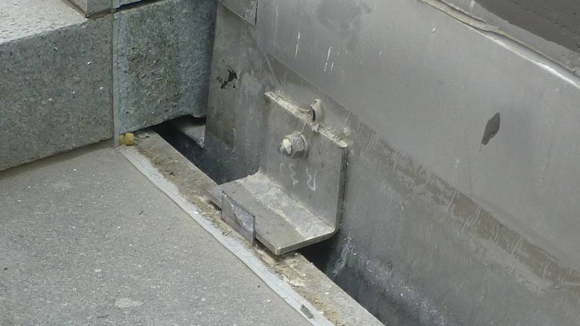
anchors are often concealed in recesses cut into the stone. In the case of the kerf anchorage, the vertical leg of a bent plate or tab anchor is fit into a slot in the stone cladding unit. Figure 2 illustrates a kerf anchorage configuration using bent plate anchors and grout filling the space between the bent plate and the stone. Although the focus of this article is not on anchor design approaches, the kerf/grout anchor combination is the contextual backdrop of the minimally destructive concealed damage assessment techniques discussed below.

Depending on the anchor characteristics and case-by-case design/construction/loading outcomes, the interface between the anchor and the stone or the anchor and the structure can sometimes experience distress in service. The primary concern associated with dimension stone cladding distress is the potential for stone material to become loose and present a falling debris hazard.
Several guidelines have been developed describing best practices for the assessment of dimension stone cladding including ASTM C1496 – Standard Guide for Assessment and Maintenance of Exterior Dimension Stone Masonry Walls and other publications, which may be referenced in local facade inspection ordinances. Though useful, these references often do not focus on identifying whether concealed distress may be present.
Concealed distress, (i.e., that which is not visible on the exterior surfaces of the facade), can sometimes be present in the form of anchorage and/or stone deficiencies. Concealed anchorage deficiencies may include anchor corrosion, inadequate engagement between the anchor and the stone, or an inadequate connection between the anchor and the building structure.
Concealed stone deficiencies can include in-service cracking or spalling as a result of excessive loads, building movement or other conditions. One such condition assessed by the authors involved a case where grout was used to fill the kerf slot in the stone around the bent plate tab, and when exposed to water, the gypsum-based grout exerted expansive outward stress on the stone adjacent to the kerf tabs, resulting in the development of cracks and spalls on the backside of kerfs (Figure 3). This case presented the authors with a scenario of evaluating minimally destructive methods to detect the presence of concealed damage as an important part of the overall facade assessment program.

Comparing Minimally Destructive Methods for Detecting Stone Cladding Concealed Damage
Minimally destructive evaluation methods can, for the purposes of comparison, be categorized as either “direct” observation methods that provide firsthand visual verification of concealed conditions and “indirect” methods that rely on technology to produce graphical/numerical data that must be interpreted and calibrated by the personnel conducting the work, thereby producing more subjective results. These categories are used to organize the concealed distress evaluation methods reviewed below.
Direct Methods
Visual Inspection
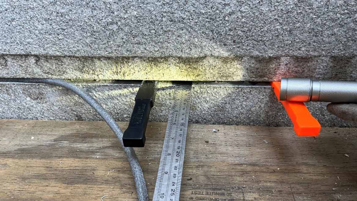
Visual inspection includes the close-range (i.e., hands-on) evaluation of dimension stone cladding panels using hand tools such as flashlights and mirrors to observe the edges of panels and anchors through panel joints following removal of perimeter sealant or mortar while the stone panel remains in place (Figure 4).
As a direct observation method, visual inspection can identify the possible presence of concealed distress. The minimal equipment required to perform visual inspection also makes it relatively cost effective on a panel-by-panel basis.
Although a direct observation method, visual inspection is limited to panel surfaces and anchors visible through perimeter joints. Features of the exterior wall, such as through-wall flashings or adjacent panels that project beyond the subject panel, can obstruct the view of the panel face and edges (even when joint sealant or mortar is removed) which limits the effectiveness of through-joint visual inspection.
Borescope
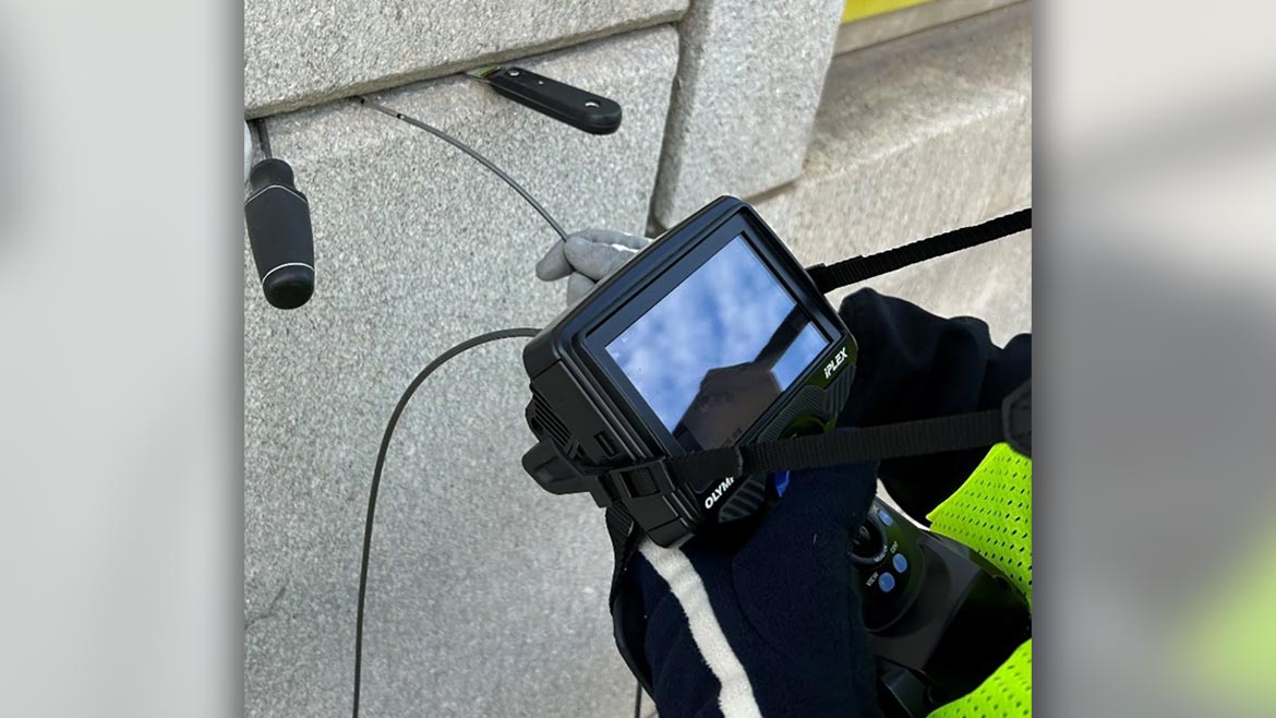
Borescope evaluation consists of inserting a video camera at the end of a flexible cable into the panel joints following perimeter sealant or mortar removal to observe conditions beyond the exterior face of the stone. A wide variety of borescopes are commercially available with different features and price points, with some higher-end models possessing joystick controlled articulating heads and adjustable illumination sources and zooming capabilities.
Similar to visual inspection, borescopes enable direct observation and documentation (using instrument display, photograph/video features of borescope instrument) of concealed conditions but provide the added benefit of allowing inspection of areas that would otherwise be inaccessible with visual inspection alone (Figure 5). The length of joint sealant or mortar removal can be as small as the width of the joint to allow for insertion of the borescope head. In many cases the borescope images can clearly identify the presence of concealed distress.
Despite their merits, borescopes can sometimes present drawbacks that can limit their effectiveness. Conditions that obstruct the path and/or view of the borescope, such as the presence and configuration of through-wall flashing, materials (e.g., grout/mortar) within the cavity and narrow panel joints can all limit borescope effectiveness. Additionally, the specific equipment can have its own limitations. A flexible borescope cable can be bent to view conditions around corners; however, the flexible nature of the cable also makes it prone to unintentionally bending over an unsupported length. Stiffer and/or thicker borescope cables may help resolve this limitation, but create their own challenges for the user as stiffer cables can be difficult to rotate and thicker cables may be too large to insert into panel perimeter joints. Additionally, the clarity of the images produced by the borescope varies depending on factors such as lighting conditions, angle at which the surface is viewed, glare on the display screen from sunlight, the size/orientation of the feature being observed and distance from the camera. Such conditions will in some cases diminish the accuracy of observations and/or create
increased reliance on the user’s interpretation (and therefore subjectivity) of the images produced.
Indirect Methods
Ground Penetrating Radar (GPR)
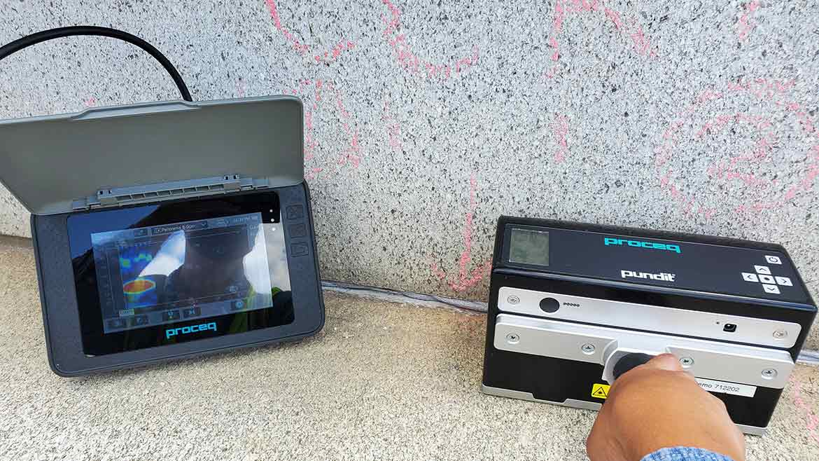
A GPR is an instrument that contains an electromagnetic wave transmitter and receiver that is rolled over the surface of the material being evaluated. When the waves interact with materials of varying electrical conductivity and dielectric properties, the GPR can identify depths, geometries and material types of concealed conditions (Figure 6).
The GPR instrument can scan up to the edge of a material (notwithstanding surface articulation obstructions as described below) without affecting clarity of the output data. A GPR instrument requires relatively straightforward calibration on the material being scanned and covers a continuous path during each scan (instead of a discrete area). These factors allow for relatively quick evaluation of larger areas.
GPR scanning is an indirect evaluation method. The inherent uncertainty of indirect evaluation methods requires calibration using direct verification such as unobstructed borescope images or hands-on observations of the panel backside during destructive panel removal. Moreover, the GPR antenna width may be considerably wider than the features under observation, which will tend to affect the intensity of the features under observation as any scan at a feature will essentially be an average of the feature and the adjacent materials, based on their respective widths. The impact of this phenomenon can be reduced by utilizing post-processing software
provided by some equipment manufacturers. Lastly, the body of the GPR instrument is significantly larger than the antenna within the body that transmits pulses of electromagnetic energy and measures the reflected energy that returns. Accordingly, projecting adjacent facade elements and tight corners can obstruct the antenna from scanning the edges of panels.
Ultrasonic Echo
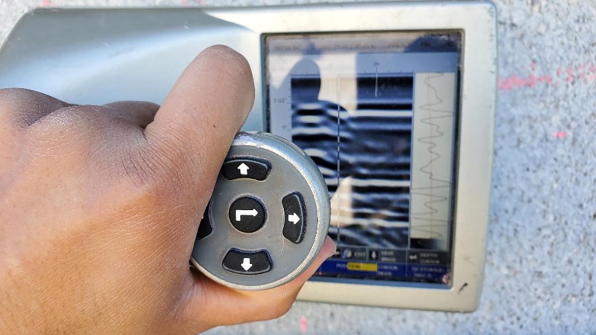
An Ultrasonic Echo (UE) instrument, also known as the Ultrasonic Pulse Echo, transmits ultrasonic stress waves into a material and measures the reflected waves that return. With this method, the instrument is intended to detect the presence of discontinuities cracks, voids or different materials by reflecting waves back to the receiver differently than a uniform solid material would (Figure 7).
Utilizing the UE instrument scan data requires interpretation of the graphical instrument readout. The readout depicts the reflection of ultrasonic stress waves that have been transmitted from and returned to the instrument. The UE instrument scanning data typically produces readouts that may depict anomalies when scanning dimension stone panels.
However, based on the author’s experience, anomalies produced by the UE instrument do not correspond particularly well to known concealed stone distress (which were captured by other direct evaluation methods).
Infrared Thermography
Infrared Thermography (IR) measures variations or anomalies in the emission of thermal radiation from the material’s surface. Anomalies are evident during heat-flow conditions such as heat flowing from a hot material to a surrounding cold environment. Object surfaces emit infrared radiation at rates that correspond to the temperature of the object (i.e., the hotter an object is, the more radiation it emits). By detecting radiation emitted from surfaces, an IR camera allows the instrument operator to visualize the apparent relative temperature of those surfaces.
IR surveys can be used to differentiate between different materials. In the context of dimension stone cladding, an IR survey may be useful to identify the presence of concealed metal elements, such as anchors, due to the difference in thermal conductivity. If significant stone distress is present such that the panel thickness is reduced over a large area, then this condition may possibly be visible as a thermal anomaly (i.e., present differently than typical anchor locations) during survey.
Although IR thermography can be used to identify the presence of anchors, it cannot provide information related to the condition of the anchors or whether distress exists at the anchor/stone interface. Minor to moderate concealed stone distress is likely not to affect the heat flow through a panel such that it can be identified through IR survey.
Analyzing IR data requires interpretation and pattern recognition to differentiate thermal patterns that are likely associated with concealed conditions and thermal patterns caused by other sources such as thermal shadows from adjacent surfaces, thermal reflections from nearby structures and materials, and differences in materials. Accordingly, destructive openings would be prudent to verify thermal anomalies represent actual concealed distress. IR cameras are useful tools for various other types of facade assessments (such as detecting air leakage and thermal discontinuities), but the authors have found them to have relatively minimal utility for use assessing concealed dimension stone cladding distress.
Surface Sounding
Surface sounding is a common qualitative stone cladding evaluation method that refers to striking the surface of the stone panel with a soft mallet and listening to the resulting sound. When struck, sound material allows for unimpeded transfer of sound waves through the material which produces a clear ringing sound. Delaminations or other discontinuities within the material impede the transfer of sound waves resulting in mute or hollow sound with little resonance.
The effectiveness of surface sounding to identify concealed distress relies on the personnel evaluating the facade interpreting variations between the sounds produced when striking the surface of a panel at and away from differing conditions. Based on the author’s experience, surface sounding can be useful for identifying varying support conditions. For example, areas away from anchor locations tend to produce a sound with relatively increased reverberation (i.e., ringing) compared to at an anchor location.
Concealed stone distress on the other hand cannot be consistently/reliably identified through surface sounding as variations between sound and distressed stone are not always clearly distinguishable. The subjective nature of surface sounding would require destructive openings such as panel removals to verify results even if a distinguishable variation were to be identified through sounding. Additionally, as the thickness of a dimension stone panel increases, the reverberation produced from sounding becomes more uniform, further reducing its effectiveness.
Other Methods
Other nondestructive and minimally destructive facade cladding methods have been developed throughout the forensic investigation industry, including those that use high-energy equipment such as X-ray, gamma-ray and neutron radiography. The authors find that in the context of dimension stone cladding assessments, these methods have cost and safety/logistical challenges that make them appropriate for general discussion, but less likely to be practical to deploy on a scale larger than a localized investigation.
Closing
During any facade assessment that includes dimension stone cladding, concealed conditions may require investigation, and the experienced facade professional uses their experience and judgement to devise a rational assessment plan. While traditional visual inspections can identify exterior surface-level distress, minimally destructive methods such as borescope imaging and ground-penetrating radar, when used in conjunction with localized destructive openings for data calibration purposes, can provide valuable insights into hidden concealed distress such as where the stone panel interfaces with the anchor. Other methods and instrument technologies, depending on the specific facade characteristics and physical conditions, may also be considered as part of a scaled assessment program, but in the authors’ experience provide less utility. Finally, each method will have its merits and limitations, requiring careful selection based on site conditions, accessibility, user training and other factors.

Tom Chmill
Senior Project Manager at Simpson Gumpertz & Heger (SGH) Washington, D.C. office. Specializes in investigating, evaluating, and repairing existing buildings and structures, focusing on historic and contemporary exterior wall, roofing, and below-grade waterproofing systems.

John Karras
Principal at Simpson Gumpertz & Heger (SGH) Washington, D.C. office. Provides building enclosure consulting expertise for owners, architects, and contractors, spanning facades, below-grade waterproofing, roofing, and glazing systems.

Myrto Ripp
Former Project Consultant at Simpson Gumpertz & Heger (SGH) Washington, D.C. office. Assisted with design and investigation of enclosure systems on buildings in Washington, DC, and surrounding region.
Looking for a reprint of this article?
From high-res PDFs to custom plaques, order your copy today!


