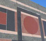
For a 1980s stone cladding design, the original thin-stone stone "mosaic" pattern consisted of six different color stones in many different shapes.
Design of dimensional stone veneer is a straightforward process when the stone sizes are similar, utilize the same material and are connected to an appropriately framed structural backup. However, if stone panels of different sizes and shapes are part of the architectural vision and the existing backup wall limits the location of anchors, the designer must be creative and meticulous in the cladding design.
In this article, we discuss a rather unique 1980s stone cladding design that presented a granite "mosaic" using stones of various size, color and shape. We also present the challenges and lessons learned during the troubleshooting (investigation) of the existing facade and the design of a new dimensional stone cladding sympathetic to the mosaic theme, while minimizing changes to the existing backup system.

Original cladding
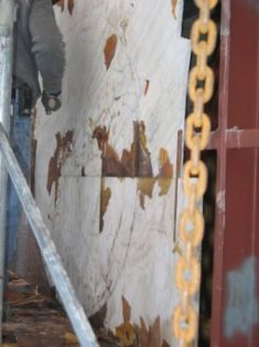
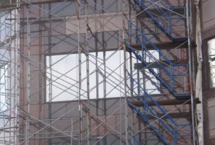
Our work focused on a six-story tower that was originally clad with a thin-stone veneer consisting of polished granite of various colors and various shapes in a pattern similar to running bond (Photo 1). The owner asked us to investigate the cause and significance of out-of-plane movement of some granite panels near the top of the tower.The original construction drawings showed concrete masonry unit (CMU) walls behind the granite cladding, but did not show the attachment of the granite to the CMU walls. During our investigation, we found that the original cladding primarily consisted of a composite panel made up of several thin granite stones (approximately 3/4 inches thick) attached to larger marble panels (approximately 1 inch thick) with epoxy and randomly spaced metal dowels. The marble panels were connected by kerf anchors to steel trusses -- not CMU as shown on the drawings (Photo 2). At the time of our investigation, the granite in the composite panels was separating from the marble due to adhesive failure of the epoxy (Photo 3).
Replacement cladding
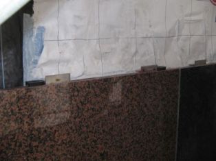
In our design of the new stone facade, our goal was to retain some of the "mosaic" features, while requiring that each stone panel be mechanically attached to the structure. To do this, we utilized four granite color types that matched the stone of four stones from the original construction: Impala Black, Baltic Brown, Azelea Pink and Taivassalo, as well as 10 different panel sizes. Due to the geometry of the existing steel trusses, which we reused to support the panels, the horizontal joints in the panels are aligned and the vertical joints are staggered to create a running-bond type pattern to keep with the "mosaic" appearance (Photo 4).New stones are anchored to the steel trusses with stainless steel anchors that are embedded in kerfs cut in the top and bottom edges of each panel (Photo 5). Our analysis of the trusses showed that intermediate horizontal members (angles) are not adequate to support the dead weight of the panels. Because of this, the weight of the panels is supported by gravity anchors fastened to the face of the bottom chords (channels) of the trusses. The bottom chords are located at every third row of panels, and subsequent rows of panels are stacked and shimmed to transfer the gravity loads to the gravity anchors. Wind anchors are provided at the top and bottom edges of each panel, and they are typically located at the quarter points of wide panels or at the center of narrow panels. In some cases, one wind anchor supports two panels (the panel above and below), but in many cases, due to the staggered vertical joints, separate anchors are required. This required thoughtful planning and positioning of the vertical joints to achieve the design aesthetic and allow positioning of the anchors at the quarter points or center of the panels, depending on the panel width.
Because the gravity anchors are fastened to the face of the bottom chord, they permit only small vertical adjustment in the field. The wind anchors could not be fastened to the vertical face of the intermediate horizontal members because our analysis showed the transfer of the wind load in this manner produces large torque of the existing angles. Instead, the wind anchors are attached to the horizontal surfaces of the angles. One advantage of attaching to the horizontal surface is that the flat horizontal leg of the anchor permits ease in positioning the anchor to establish horizontal control to maintain the face of the stone. Vertical adjustment of the stones is done by the use of plastic shims, for small (1/4 inch or less) variations, and by steel shims welded to the anchors for large variations.

Another challenge we encountered was finding replacement granite that met both the aesthetic and strength requirements of the design. The contractor submitted proposed replacement stones along with testing data provided by the stone quarry for each stone type. Matches for the Baltic Brown, Impala Black and Azelea Pink stone types were approved with the first submittal. It was more difficult to find the Taivassalo stone, a red granite from Finland, or an acceptable substitute. The first two stones submitted as an alternate were Canada Rose and Oklahoma Red. Both were rejected because they did not match the color of the existing Taivassalo. Eagle Red, the third red granite submitted, was a good aesthetic match, and was approved pending results of required laboratory tests. We tested the Eagle Red granite in accordance with ASTM C880 for flexural strength in our laboratory and found that the sample of stone consistently fractured at less than 1,000 psi, which is less than the strength required by ASTM C880, which is 1,200 psi (Photo 6). The low strength of the stone made it unsuitable for larger panel sizes. Finally, Balmoral TLO granite was submitted and approved, as it was a good aesthetic match to replace the Taivassalo stone, and it passed the flexural strength test -- averaging a strength of 1,800 psi.
Key concepts to consider when designing a thin-stone veneer cladding include:
1. The architect's vision for the building,
2. anchorage of the panels to the supporting structure,
3. layout of the panels and anchors to accommodate geometric and strength limitations of the supporting structure,
4. flexibility in the design to accommodate unforeseen conditions, and
5. necessity to verify testing data to be sure the requirements of the design are met.
Each of these design considerations are further complicated when designing a cladding system for use on an existing building.
AUTHORS' BOX
Katherine S. Wissink, LEED AP is a project engineer at national engineering firm Simpson Gumpertz & Heger Inc. (SGH). She is involved in the design, investigation, construction litigation support, construction administration and peer review of building envelopes. She has experience with a variety of wall and roofing systems, including dimensional stone cladding, multi-wythe masonry walls, brick veneer walls, stucco wall systems and slate roofing systems. Wissink can be reached at kswissink@sgh.com. Annemarie Rabazzi, P.E. LEED AP is a project engineer at SGH. She is involved in the design and investigation of building envelopes, construction administration of building envelope repairs and peer reviews. She has experience in a variety of wall and roofing systems, including brick and granite veneer walls, dimensional stone cladding, EIFS and stucco wall claddings, curtain walls, single-ply and built-up roofing systems, and shingle and slate-steep roofing systems. Rabazzi can be reached at alrabazzi@sgh.com.


